
Phaseback Math
An Explanation of What Happens When The Phaseback VSGR (Voltage Stabilizing Ground Reference) Corrects A Power Quality Problem
Written by William Hinton, Director of Engineering and Dan Princinsky, President
What does the Phaseback VSGR Do?
The Phaseback VSGR corrects voltage imbalance and prevents voltage surges in the most efficient manner possible. Unlike most power quality products, the VSGR uses voltage control instead of current control. The Phaseback VSGR uses tenths or even thousandths of an amp to do this. Compare this to the hundreds or thousands of amps used in traditional MOV/TVSS, whose operation is based on current control.
Why Balanced Voltages Matter: NEC and IEEE Standards
NEC and IEEE recommend that motors should not run on a power system with a voltage imbalance above 2 to 3 percent, nor should ground current be sent to the hull of a vessel.
This blog will demonstrate the VSGR’s unique ability to efficiently reduce both ground current and voltage imbalance.
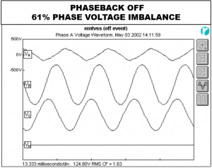
Voltage Waveform Imbalance
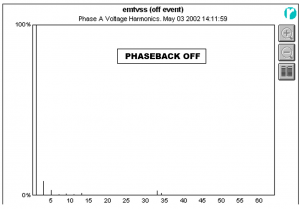
Graphic #1 (Phaseback OFF) shows the (3) phase voltages: with A being low, B was high, and C was the closest to the nominal 277 volts that all three phases should have read.
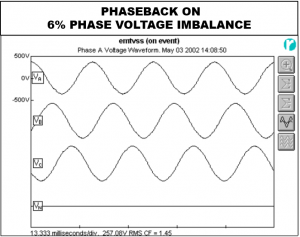
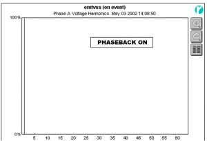
Graphic #2 (Phaseback ON) shows the (3) phase voltages, with A being raised up, B was pulled down, and C still looked like the nominal 277 volts that all three phases should have read.
Now the voltage imbalance was about 6%, all the machines ran as they should, and Phaseback alarmed the condition. No damage done.
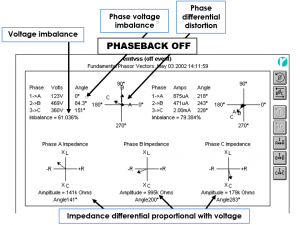
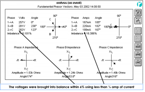
Phase Voltage Imbalance
Graphic #1 (Phaseback OFF) shows the phase voltages:
A 123 volts @ 0°,
B 469 volts @ 84.3°,
C 360 volts @151°
Graphic #2 (Phaseback ON) Phase voltages:
A 257 volts @ 0°,
B 281 volts @ 236°,
C 282 volts @ 123°.
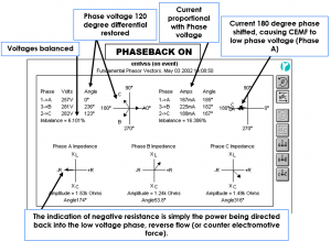
Phase currents were all in phase with each other, and 180° out of phase with the lowest phase voltage (Phase A) to push it up.
How much current did it take to correct the 151.8° phase shift in phase B voltage and a 28° phase shift in the C phase voltage?
The current in Phase A was 0.167 amp, the current in phase B was 0.225 amp and the current in phase C was 0.188 amp. It took only 0.225 amp to pull down the phase B voltage from 469 to 281v, and it took only 0.188 amp to pull down phase C voltage from 360 to 281v, and it took only 0.167 amp to pull up phase A voltage from 123 to 257v.
Phase Voltage Harmonics
Graphic #1 (Phaseback OFF) shows the voltage harmonics without the Phaseback
Graphic #2 (Phaseback ON) shows the voltage harmonics eliminated with the Phaseback
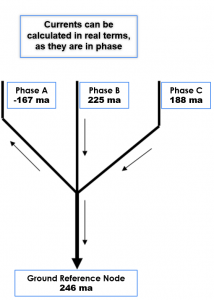
Phaseback Math
Unlike the circuits detailed in literature, and manuals for resistance grounding circuits, Phaseback does not use a “summing” junction. Phaseback takes energy from the phases with higher phase voltage and redirects this energy to the low phase voltage.
All three currents are in phase with each other, and approximately 180° out of phase with the phase having the lowest voltage. This phase shift is automatic and instaneous.
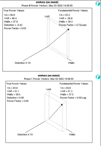
Power Consumption
Notice the power directed back into phase A (negative wattage of -42.8w) with 98% power factor. Negative wattage indicates the power was being pushed back into phase A to correct the low voltage condition.
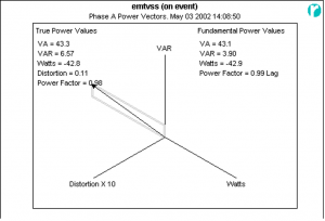
Notice the power used by phases B and C: 37.9 and 38.4w.
There exists only one product that has been proven to eliminate all power quality problems associated with unbalanced voltage. The Voltage Stabilizing Ground Reference (VSGR) from Applied Energy, LLC is the world’s only laboratory-tested, industrially-hardened, energy-saving, energy-efficient, future proof, harmonic noise eliminating, ground fault/arc flash preventing, lightning arresting, EMP mitigating system.
If Phaseback isn’t already installed where you work, ask your manager: Why not?